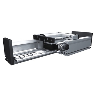
DLM linear motors

Electric linear drive. Three profile size groups: 120×60, 160×80, 200×100. Aluminum linear unit with an internal, double roller linear guide for high loads. The carriage is driven by an electric AC synchronous linear motor integrated within the aluminum linear profile. Repeatability of 0.05mm. Maximum linear speed of 8 m/s. Maximum feed force of 13.8 kN.
DLM Linear Motors
Features of DLM Electric Linear Motors:
- The body of the linear motor guide consists of a rectangular aluminum profile.
- Two roller guides are integrated with ten or twelve guide rollers, depending on length and load.
- The DLM linear motor axis operates based on the principle of a linear three-phase synchronous motor.
- The secondary part is equipped with permanent magnets and serves as the stator.
- The primary part acts as the rotor and has three-phase windings.
- Magnetic attraction creates a force effect between the primary and secondary parts.
- Multiple guiding carriages (primary parts) can move independently along the guide profile.
- Maximum length of a single piece: 6000 mm.
- The linear axis can be connected to any T-slot profile.
- By default, the carriage is mounted on ten or twelve adjustable rollers, keeping it in a fixed position.
- The number of rollers can be increased when extending the carriage.
- Aluminum linear unit with an internally placed double roller linear guide for the carriage.
- The carriage is driven by an electric linear motor integrated within the linear profile.
- Linear motor carriage mounting: via T-nuts.
- Linear unit mounting: via T-nuts or a mounting kit.
- Max. attraction force (Fa): 11,000 N.
- Max. permissible load (Fz): 2,800 N.
- Measurement system: LE100 linear encoder HTL (24V) / TTL (5V).
- Optional: Design with a flexible bellows cover.
- Recommended servo drive with motion controller: SD6 from Stober.
Technical Data of the LE100/1 Measurement Encoder
- Supply voltage: 10.5 – 30 V(DC), 5 V(DC) ± 5%
- Current consumption: <25 mA at 24 VDC; <50 mA at 5 VDC
- Protection: Reverse polarity protection
- Housing: Metal
- Output signals: Sine A, B, 90° phase shift
- Output current: I out max. 5 mA per signal track
- Signal amplitude: Approx. 1 Vpp
- Max. linear speed: 10 m/s
- Measurement accuracy: Depends on interpolation electronics
- Accuracy class: ± 0.1°
- Repeatability accuracy: Max. ± 1 μm
- Scale distance / sensor: 0.1 – 0.4 mm
- Operating temperature: -10°C to +70°C
- Storage temperature: -30°C to +80°C
- Resistance class: 3, according to IEC 801
- Certification mark: CE
- Protection class: IP67 with reading direction S
LE100/1 Linear Encoder
A contactless measuring unit with an integrated analog signal output (sine wave 1 Vpp).
The LE100/1, together with the MB100 magnetic tape and interpolation electronics, forms an open and robust linear measurement system.
Available Documents in English:
- data-sheet-le100-1.pdf – Technical parameters of the LE100/1 magnetic sensor
- quick-start-guide-le100-1.pdf – Quick start guide for the LE100/1 magnetic sensor
- user-information-le100-1.pdf – User manual for the LE100/1 magnetic sensor
Features of the LE100/1 Linear Encoder:
- Easy installation
- LED status display
- Signal period of 1000 μm (analog)
- MB100 scale
- Reference signal (optional)
- Resistant to dust, chips, and moisture
MB100 Magnetic Tape
The base material is magnetized at specific intervals and permanently bonded to the carrier tape. A special adhesive tape is prepared for mounting. The set includes an additional stainless steel masking tape.
Catalogs
DLM_EN.pdf – Datasheet for DLM Bahr electric linear motors
linearencoder_dlm_dsm_de.pdf – Datasheet for LE100/MB100 linear measuring encoders
DLM_INSTRUCTION_EN.pdf – Installation instructions for DLM electric linear motors
ACCESSORIES_EN.pdf – Accessories for linear drives and linear guides Bahr
