Synchronization of Drive Axes
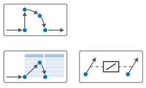
Drive Synchronization
Drive Based Synchronous Application
In the DS6 program for programming SD6, SI6, and SC6 motor controllers
The sixth-generation Drive Control Suite (DS6) software for STÖBER drive controllers offers convenient functions for efficient configuration and quick project commissioning. It is ideal for synchronized operation of multi-axis systems or simple single-axis applications. The DS6 software includes the Drive Based Synchronous application, which provides versatile motion control solutions based on single- and dual-axis controllers from the SD6, SC6, and SI6 series, utilizing position, speed, and torque/force control modes. Standard commands related to these control types are divided into two modes: command-based control and motion block control. Additional features for monitoring process variables, such as positions or speeds, ensure enhanced user comfort.
DS6 Program Overview
The DS6 program is user-friendly. Setting up a new project requires entering basic information. In the configurator, you select the size and type of drive controller, the type of optional cards, and the level of installed safety functions. The next step is selecting the motor type and size, as well as the application type you want to use. In this step, you will choose the Drive Based Synchronous application.
Drive Synchronization
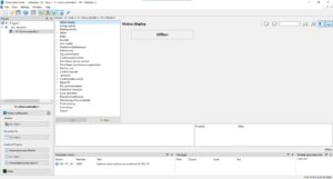
After completing the initial configurator, you can program your axis by clicking on the relevant axis number. A configuration options list will appear. The first element is the status of your controller. If not connected to the device, the status will display as offline.
Configuration Tabs:
- Power Supply Tab: Input the device’s power supply voltage limits.
- Braking Resistors Tab: Program the braking resistor in the system.
- Motor Tab: View and adjust information about the connected motor, read temperature, and set current limits. Conduct winding tests, phase connection verification, and motor calibration.
- Brake Tab: Configure brake behavior and activation times, conduct brake tests, and perform brake bedding.
- Encoders Tab: Set the type of encoder used on the motor and configure additional positioning encoders if available. Master encoder scaling can also be defined here.
- Axis Model Selection: Choose between a rotary or linear axis and configure scaling based on gear ratio and measurement units. Define position limits, end stops, speed limits, acceleration, and permissible torque.
Advanced Features:
- Predictive Maintenance: Check the wear level of the gearbox working with the motor equipped with an electronic nameplate.
- Referencing Tab: Select the positioning referencing method using sensors, limit switches, or other combinations.
- Jog Control Panel & Control Panel Motion Tabs: Perform manual test drives and motion command tests to verify correct scaling and limitations.
Drive Based Synchronous Application
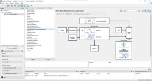
This application tab allows you to select the synchronization command input method: command-based control or block-based control.
Command-Based Control
You can assign values to control words to execute motor motion, such as the j40 command for motion. Standard PLCopen commands like MC_MoveAbsolute enable absolute motion to a defined position. Command-based control is suitable for master PLC devices. Commands for synchronization include MC_GearIn, MC_CamIn, and their disengagement counterparts MC_GearOut. Configure master signal sources in the Data Source Tab, including analog signal inputs for speed or torque control.
Block-Based Control
Define blocks containing commands, target positions, and dynamics. Block execution can be triggered via digital inputs, eliminating the need for a PLC to start motion. Sequence execution can be triggered by events like the completion of a block or digital signal interruptions.
Monitoring and Tuning
- Motion Core Tab: Monitor programmed motion.
- Control Cascade Tab: Adjust position, speed, and current regulators. Includes autotuning functionality and an oscilloscope to plot up to 12 parameters simultaneously.
Communication and Safety
- Industrial Communication: Program EtherCAT, Profinet, or CAN communication depending on the motor controller type. Monitor connection status, map variables, and adjust synchronization timings.
- Protective Functions: Configure protective features for the servo drive, such as phase loss or motor connection loss detection.
Final Features
- Drive Status: View software version, operating hours, and fault counters. Save configurations and restart the drive as needed.
- Parameter Table: Use an A-Z parameter list with a search feature for quick adjustments.
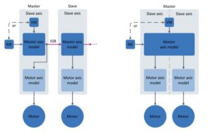
Synchronization Models
-
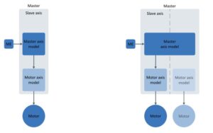
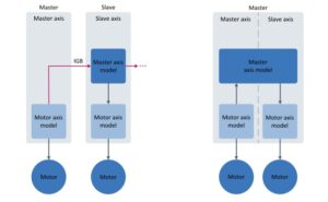
Virtual Master or Encoder (Multiple Slave Drives):
Signal is delivered via a virtual master or encoder. For dual-axis controllers, both axes follow the master. Synchronization in SD6 drives is provided via the IGB bus. -
External Encoder (Individual Slave Drive):
Signal is delivered via an encoder, with only one slave drive in operation. -
Current Axis Position as Master (Multiple Slave Drives):
Signal is delivered from the current position of the master axis. In dual-axis drives, the second axis follows the master.
For detailed command descriptions, refer to the Motion Commands Manual (V 6.5-H or higher):443046_02_HB_Drive_Based_Synchronous_en.pdf
For more details, contact www.demero.pl or email biuro@demero.pl.
